Sunday, August 23, 2015

A New Kind Making

3D printable plastic designs definitely have their place, but nothing beats fusing metal by way of super-heated metal. There's something violently entertaining about arc welding.  The smoke, the sparks, the danger.

It's very much like firing a gun.  Only difference is that you're making things, and not destroying them with supersonic bits of lead and copper.

Introducing the new tool in the MakerJeff toolbox, the Lincoln Handy Mig welder!


The feed mechanism is very much like a filament extruder.


I'll be using flux-core wire until I can get a gas setup going.  The go-to flux core wire that most people tend to use is the Lincoln Electric NR-211-MP.  Again, very reminiscent of a spool plastic filament.


Also brushing up on Solidworks, digging deeper into the Weldments and FEA simulations.


I've got a few fun projects lined up to test what this welder can do, so stay tuned!

Friday, July 31, 2015

TANK3 Preview!

Here's a preview of a tread-based robot that I've been working on.  More details of the build to come!


Sunday, February 1, 2015

Project-Making-Of: Ms. Yang's "Bully" Horn

As part of her job as a 2nd grade teacher, my fiancee has traffic duty every day after school.  In order to save parents and children from themselves, she's forced to strain her voice with commands that really should be common sense.

Something had to be done.

Introducing Ms. Yang's "Bully Horn".

Original Photoshop concept paintover.

Based off of a Pyle PMP30 Professional Megaphone,  the "Bully Horn" needed a little bit of style. We decided on a pink glitter paint scheme, with rhinestone trim around the edges and her name.

After 3 coats of pink glitter paint and 3 coats of clear.

After disassembling the megaphone and masking off non-paint areas, I whipped out the DIY spraybooth and applied 3 coats of glitter paint and 3 coats of clearcoat.

Semi-sealing the gaps before wet-sanding.

It's not a 100% seal, but I used painters tape to help keep the water out of the battery compartment. 

Wet sanding in the bathroom sink.

 The "Bully Horn" was wet-sanded with 1000 then 2000 grit sand paper.  Special care had to be taken for undercuts and hard angles.

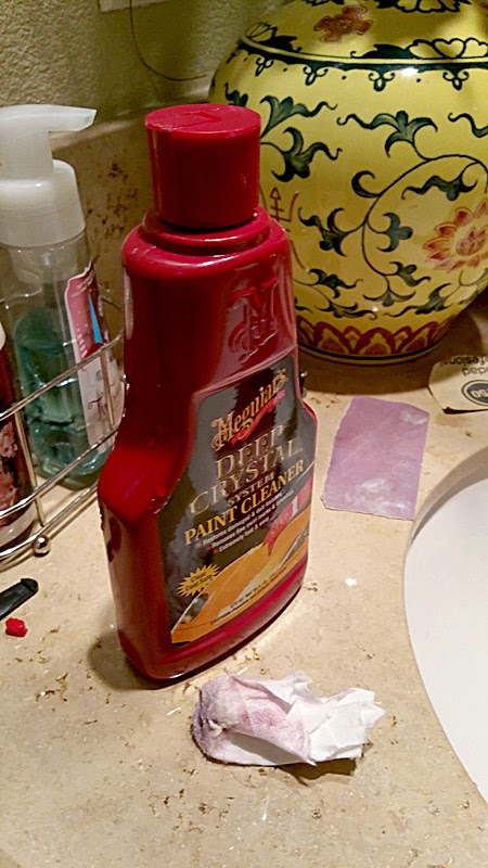
Meguiar's Paint Cleaner.

After the wet sanding, I used left-over Meguiar's Paint Cleaner to polish and clean up the micro-scratches left by the 2000 grit paper.

Reassembly of glittery-shiny "Bully Horn".

The "Bully Horn" was then reassembled to check for gaps in the paint, especially around the hinge area.  There was a bit of white still showing, so I touched it up using a nail polish brush.

Vinyl decals applied.

The decal was designed in Adobe Illustrator and cut using a Silhouette Cameo 2 personal plotter (that we named Cutter-Bot).

Rhinestones around the vinyl decal.

The Silhouette Cameo 2 also came with a wonderful software that could create rhinestone templates.  Great for aligning rhinestones to vinyl decals cut from the same machine.  For the stencil, I used a matte black removable vinyl that you can see in the background. 

Individually hand-placed rhinestones.

Each rhinestone was hand-placed and glued on using Gorilla Super Glue.  I found the quickest method of application was to create a small pool of glue to dip the rhinestone in, then immediately place it where it needs to go.

Happy fiancee with 30 watts of vocal power.

After 2 months on and off manual labor (most of which went to hand-placing the rhinestones), this 2nd grade teacher is now armed with 30 watts of voice amplification power.  All for the purpose of keeping children (and their grown up versions) safe from themselves, of course.

Wednesday, January 14, 2015

3D Printing: E-Bike Miniature Frame Joints

I miniaturized the joint design to build a straw mockup of the frame.  Nothing beats the touchy-feely aspect of a physical mockup!


Being able to hold it in my hands gave me a new direction on the front-end design of the frame.  The new design moves the lower connection to the fork tube closer to the wheel.

Also, received my order of XTC-3D brush-on coating for 3D printed parts.  It's supposed to self-level as it cures so it should cut down finishing time by quite a bit.  I'll do some tests this weekend and report back what I find.


Tuesday, January 13, 2015

3D Printing: E-Bike Frame Joint

I'm using these joints to build the PVC frame of the E-Bike. They'll most likely be solid urethane resin casts for a couple of reasons.

The primary reason being that these joints take about 4-5 hours to print with a 50% infill.  An OOMOO 30 silicon mold would require roughly 6 hours to cure, but each Smoothcast 320 resin part has a demold time of only 10 minutes.

I need about 16 of these.

Another reason is that the cast joints would be solid and therefore stronger.  ABS has stronger material properties than Smoothcast 320, but the nature of the FDM (FFF) process makes the part prone to delamination under stress.

Here's a quick comparison between the two materials:

  • Smoothcast 320:  (datasheet)
    • Tensil strength: 3,000 psi
    • Compression strength: 3,650 psi
  • ABS: (datasheet)
    • Tensil strength: 5,532 max psi (based on Makerbot filament)
    • Compression strength: 7100 max psi (based on Makerbot filament)
As you can guess from the pictures below, I now split tricky parts in half when printing.  They're merged either with ABS glue, super glue, or JB Kwik Weld.

I used to split the parts directly in Solidworks, but for 2015, I'm trying to ween off commercial software and rely on open source tools wherever I can.  

This part was:
The toolchain becomes much longer when going the open source route.  However, with the exception of the 3D printer itself, everything is free and available for Windows, OSX, and Linux.  More to come!


Saturday, January 10, 2015

3d Printing: Plastic Thrust Bearing

As a personal challenge for 2015,  I'm trying to ween myself off of commercial software and focus on using open source software.  This was modeled in FreeCAD, a wonderful open source parametric modeler available for Windows, OSX, and Linux.

This is a test for a thrust bearing design as part of a work-in-progress all-plastic electric bike.


3D Printing: Heat Shields for Larger Prints

Not 100% sure where I read it first, but the idea of using a heat shield (technically a "draft" shield) really does work! Usually on my Replicator, a part that spans across the entire build platform will curl up on both ends.

However, using a 0.8mm thick heat shield (single 0.4mm shell all around), this client part came out perfectly straight. Also helped with the start and stop filament gapping that occurs with accelerated printing.


Sunday, October 19, 2014

Acceleration and PyPy

While trying to dial in the acceleration on my Replicator original, I ran across a post regarding the alternative "just in time" Python compiler, PyPy.

http://mbot3d.eu/install-pypy-to-accelerate-replicatorg-slicing/

It offers much faster slicing when using Replicator G and Skeinforge.  I tested PyPy out and can confirm that it indeed does take much less time, about 1/3rd of the speed of Python 2.6!

On a top secret unidentified part:
  • Python 2.6:
    • 2 minutes, 59 seconds to slice.
  • PyPy:
    • 1 minute, 1 second to slice.
Needless to say, I switched over and haven't looked back since.  

On the acceleration front, after replacing the Makerbot Mightyboard a while back, I never got around to setting up the acceleration settings.  For a while, I was only printing at about 40-50mm/s with low acceleration settings before the machine felt like it was rattling loose.

After dialing in the settings, I'm now printing at about 75-85mm/s with overall much quieter operation.  : )

Tuesday, January 14, 2014

The New D.I.Y: Design-It-Yourself

I've had the Makerbot Replicator for a little over a year and a half now and I've come to realize just how much a 3D printer has changed my life.  I love making things, both in the real world and in the computer.  My two worlds collided the day I got my printer up and running smoothly.

DIY projects used to require that I peruse the aisles of hardware stores and dollar stores for the required bits and pieces to kitbash.  I still love looking at dollar stores and supply stores, but now it's more for "raw materials".  

For example, I can get 3 button cells for $1 at Dollar Tree, and it comes with free LED circuit and reed switch.  It was also cheaper for me to buy a $17.99 sheet metal rack from IKEA than to pay nearly $100.00 for the sheet metal needed on the Quad-Quad MK1 blades.

Since the Makerbot: Replicator came into my life, things that used to exist only in the computer can now have corporeal form.  Things that had to be shaped through blood, sweat, and tears, can now be designed in the computer!

Well, actually, it starts on paper.  The first thing I do when I have a random idea for a "DIY" project is to doodle out concepts on a piece of throw away paper.  Usually the first few sketches are brain dumps, and the idea that I'm drawing on scratch paper helps quite a bit with my paralyzing 'blank page' syndrome.

From there, the next generation of sketches make it in to my current sketchbook.  The sketchbooks include anything from sketches to dimensions on parts that I have at hand.  I have a library of sketchbooks for myself to recall information that has, or definitely will, skip my mind.  My girlfriend can attest to the fact that I have the memory of a goldfish, and getting worse by the years.  

Then I bring it into 3D (Solidworks or Maya) and begin the modeling process.  I start with modeling out the physical items I already have at hand.  Battery packs, PCBs, buttons, etc.  I measure the dimensions with a set of metal calipers from Harbor Freight ($8.99 on sale) and try to get these as close as possible to the real world counterparts.

After that, I model out the project parts with close attention to matching the real world part dimensions.  I take into account the print tolerance of my Replicator when building parts that need precise fitting. Note, screw holes can be drilled or bored out post-print.

When in doubt, I print out a sample and test.

Nothing's more satisfying than holding a physical piece of your digital creation in your hands after a successful print.  Even more "awesome-er" is when everything fits and works the way it was meant to.  Even if it does, there's always a way to make it better!

"D.I.Y" projects for me are no longer hand-made "Do-It-Yourself" projects of yore.  They're now "Design-It-Yourself" projects.


Monday, August 19, 2013

Extra Shells = More Efficient!

Currently working on printing a scale model of a certain luxury sport sedan for work, and realized that slicing with 2 extra shells in ReplicatorG yielded a 1.5 hour reduction in estimated print time!  Also noticed that for internal areas where ReplicatorG used to fill in a solid block, it's now printing with proper hexagonal infill.

It COULD however, be the fact that I'm also using 0.25mm layer heights instead of my normal 0.3mm as well.  Maybe areas where the extreme angles of the car surface required a solid infill layer is now supported better by the lower layer height, as well as the extra shell.  More testing is required!

Tuesday, July 30, 2013

2013.JULY.30 Update

It's been a year since I've posted anything new to this site, but rest assured, there has been no shortage of random ideas and makings.  However, I've started to realize that there is really no way for me to execute every single idea I have, due largely to the lack of time as well as funds.

As of now, this blog will become a dumping ground for all of the random ideas that I may come across.  They may be just random doodles on a napkin, or fully fledged out designs of mechanical mayhem.  Some will have pictures, some will just be text.  Some will be expanded upon, others will fall to digital ether.

I've come to realize that most of these are really just brain exercises and may never be executed.

But that's okay.  

This ensures that my brain doesn't turn into mush while playing videogames.

Monday, August 20, 2012

Quad-Quad Mark 1

This was a build I worked on several years ago that was sparked by the need to have extra rendering nodes for my 3D work.  The plan was to use easily acquired, off-the-shelf parts from your local electronics store, and build a framework that allowed 4 computers in a single enclosure.

After pricing out 4x Intel Quad-Core Q9300 bare bones machines with 4GB ram and 750gb HDD's each (yes, totally overkill for a render node but was cheap at the time), the build came out to be no more than $2500.  That's $2500 for 4 individual machines, and 16 render threads.

Including my workstation and the render server which were both Q9300 platforms, I had 24 render threads at my disposal if required.

Roughly, a 6 hour render would then become a 1 hour render.

In retrospect, it would've been easier to just BUY a rack and 4x 2U boxes to house these 4 MicroATX motherboards.  But where's the fun in that?  I took the opportunity to learn the tools required to build such a box.

PC Parts:
- 4x ASUS P5QPL-AM (cheapest ASUS mATX mobos at the time)
- 4x Intel Q9300 2.5ghz Core2Quad processors
- 4x 4gb Corsair XMS2 ram (2x2gb packs)
- 4x Rosewill (cheapy) CPU fans
- 4x Corsair 400w PSUs
- 4x Western Digital 750gb (or 640gb, not sure anymore)
- D-Link gigabit ethernet / wireless router
- APC UPS
- bulk pack LEDs (2x200 from eBay)
- bulk buttons (100 from eBay)
- Lian-Li HDD anti-vibration mounting kit
- miscellaneous wires, etc.


Structural parts:
- 2x2" square wood stock
- miscellaneous bolt and nut (I think it was 3/8")
- washers
- IKEA Hyllis (15$ for 4 planks, as well as the cheap sheet metal frame)

I scoured the web as well as local stores for suitable materials to build platters for each individual blade.  What I found was that the IKEA Hyllis galvanized sheet metal shelving system had the perfect dimensions for what I was envisioning for the Quad-Quad.

It was also only $15.00 for all all 4 platters and sheet metal support beams, cheaper than a single sheet of comparable gauge sheet metal from Home Depot.  I wasn't planning to weld anything for the mark 1 build of the QuadQuad, so the cheap galvanized sheet metal was perfect.


After finding suitable materials, I began to dimension out all the parts that would be going into the build and made foam core mockup pieces to visualize the spacing.


After dimensioning out the parts and doodling out designs on paper, I decided on going with what looked to be a 2'x2' wooden cube frame structure.  It would eventually be covered using 1/4" board panels, and feature dual 200mm fan intakes in front, as well as dual 200mm fan exhausts on the top. Inside would have vertically hanging blades that fit into notches on the support rails.  

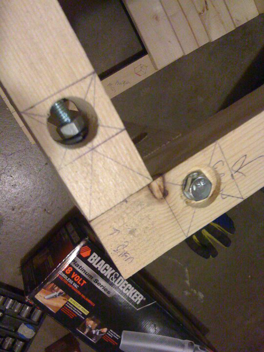
The frame would be easily disassembled in case the Quad-Quad had to be moved.  Instead of glue and nails, I decided to go with a nut and bolt configuration.  I'm not sure what this method is called, but I picked it up from browsing DIY CNC machine sites.  

For the job of building the frame, I used a Hitachi miter saw I had purchased a few months prior.  I believe it was 99$ as an Amazon goldbox deal.  It hadn't seen a whole lot of action until I started this project, which is why it looks spick and span in the pictures (as of this writing, it is no longer the case).

I decided to go with wood for the frame because 2"x2" pine were easy to cut and manipulate. 


All the wood beams had 1" holes drilled on the side as well as (I believe) 3/8" holes drilled 90 degrees perpendicular to the 1" hole.  It's a little hard to explain but you can see in one of the following assembly photos.


Once the frame was built and tested to be structurally sound, I began building out the cover panels from 1/4" thick wood.  I don't remember exactly what the type of wood was, but it was also easy to cut.  

The Harbor Freight scroll saw came in handy when cutting the 200mm fan holes in the panels.


Utilizing the sheet metal shelves from the IKEA Hyllis purchase, I began cutting to design spec using an angle grinder and a cutoff wheel.  It looks weird with the part that bends up from the plate, but I use that to connect each of the 4 platters together for stability and to hold spacing.


The hard drive mounting holes were drilled large enough for the anti-vibration grommets to be seated.


The motherboard offsets were held in place by 6-32 nuts.


After securing the motherboard and hard drive on to the platter, I held it up vertically and shook it gently to make sure the pieces held as anticipated.  Since the Quad-Quad Mark 1 wasn't planned to be a mobile platform, no more than a little shake was necessary.


Tested the hanging notches as well.


Once one platter was finished and tested, the same exact thing had to be done 3 more times for the remaining platters.


Over the years I've assembled many PCs so this part was easy peasy.  I set up a temporary install station and installed Windows XP SP2 32bit on all the nodes.  At that point, Windows XP SP2 32bit worked with all the software I needed to use.  The Quad-Quad MK2 later on was upgraded with Windows 7 Pro 64bit on all nodes.


I didn't want to blow the budget by buying power buttons and LEDs from online retailers, so I opted to buy the parts myself in bulk and made my own buttons, power, and HDD activity LEDs.


These buttons were horrible.  The contacts inside were unreliable at best.  I later on swapped out the power buttons with much nicer ones from Radioshack for the Quad-Quad MK2.


LEDs and power button connected.


All the blade platters mounted on the hanging rails!


If I remember correctly, there were 5cm's between each platter.


The chassis was moved into my room / office and was reassembled.  The PSU's as well as the APC battery backup were put into place.


The fan controller is installed on Node #1 of the Quad-Quad, assuming Node #1 will always be on before any of the others are required.


The fan controller is useless if the fans are just dangling, so I put my dad to work.  He helped thread the fans so they could be mounted to front and top panels.  


However, the top fan was never installed due to miscalculation.  There wasn't enough clearance between the top panel and the blade platters for the 200mm fan to fit, so I ended up leaving it.  I had plans to finish it and make it look pretty, but just didn't have enough time.


Fast forward toward the end of 2011, and the Quad-Quad MK1 is taken down during room / office renovations.  Months later... development for the Quad-Quad MK2 began...